Nosnap recap

Well, nosnap-nocsg is one (very) nice way to make maps. The basics of nosnap consists in manually removing all the unseen polies from a map. This way, the processor has little job to do. Maps process faster and, usually, also run faster. The only two drawbacks to this method are:

  • it requires a little bit of experience
  • it’s time consuming

This small tutor tries to eliminate the first one. The second one can be reduced only after getting used to this method.

All nosnap maps use single-sided geometry. One cubic brush is made from 6 single-sided square brushes. They are aligned with their faces (normal vectors) outwards. Now, if that brush were to be placed on a floor, the face placed on the floor will never get seen by the player. So, why not remove it? That is the essence of nosnap: removing all the polies that the player won’t get to see. The map will run better and process faster.

Normally the processor does that for the Detail 0 brushes, but with a lot of time consumed. The processor however won’t do jack shit for your Detail 1 brushes and prefabs. This poly removal can be applied to any kind of brush: hull or prefab, detail 0 or detail 1. It works perfectly.

Now this nosnap thingie can be tricky when working the hull (outer detail 0 geometry) to nosnap; if you remove the wrong polygon, you’ll get a leak.

Ok, now how do you remove the face of a cube? Well, first, you must un-join the faces of that cube. Simply select the cube by clicking on it, then hit CTRL-J. This way, you actually un join all the faces of the brush. Now delete the face that was pointing downwards. You should obtain something looking like this:

nosnap4

One hint: before un-joining the brush, move it somewhere you won’t be bothered by other brushes. Usually, I move it upwards 2048 DEdit units. Then do the un-joining and deleting part:

nosnap2

First, I moved the brush up, so I won’t be bothered by other brushes. Then I selected the polies that I wanted to remove. One simple click usually does the trick:

nosnap3

Then, deleted the faces that were unseen, by hitting the DELETE key. That easy:

nosnap4

All the remaining faces (now single-sided geometry) must have the NOSNAP flag set to TRUE:

nosnap9

The NOSNAP flag tells the processor to leave all the vertices (the lines that make the outline of a polygon) as they are. By default, the processor tries to set them on the grid. Now that’s OK if you build on the grid or if you don’t use nosnap.

However, in nosnap, if you don’t turn this flag to TRUE, you’ll get the ‘Invalid brush found at … ‘ message. Even if you ignore the error and try to run the map, you’ll find yourself facing odd things, like walls that extend towards infinite and so on.

So, when using single-sided geometry, remember to turn the NOSNAP flag for that particular brush to TRUE.

Plus, you must process your map with the extra parameter -nosnapnocsg:

pmaking6

Otherwise you’ll get a processing error like ‘Invalid brush found at …’

After un joining, deleting and setting the NOSNAP flag to true, you have two options:

  • rejoin the remaining faces (select all the polies and hit J)
  • leave them unjoined but group the together in s folder (select all the polies and hit CTRL-ALT-G)

Now this marks the separation point for two methods of work:

My way:

First one rejoins the polies and sets them to Detail 1, no matter if they were polies from the walls (that should make the hull) or prefabs (that were supposed to stay Detail 1). Now this will definitely leave your level leaking. All you have to do is make a simple hull (rectangular section) that follows the main layout of the level:

nosnap6

Ok, so this image should show you the extra hull I was talking earlier, and  the fact that it has a very simple rectangular section:

nosnap7

Here you should be able to see how the extra hull (the outer Detail 0 brushes) follow the main layout of the map, in order to create a good visibility zoning scheme.

This asks for the additional effort to create an extra hull, that follows the layout of the map. However, the simplicity of the hull (it has a simple rectangular section for crying out loud!) should make this easier. The time taken for a full optimization is very short (my 12,000 polies SP project takes few seconds through the Full Optimization stage from it’s
5 min. of total processing time).

Windebieste’s way:

From what I’ve seen from the ‘posse’ project, Windebieste works in a different way: he only rejoins the prefabs and sets them to Detail 1. The polies that make the outer walls will remain Detail 0 and UNJOINED, eventually grouped together into a folder. This way, those polies will actually create the outer hull:

nosnap8

It spares you the effort to manually create the hull. However, it takes a little bit more time to process; the ‘Full Optimization’ stage takes almost a minute for the ‘posse’ project (8000+ polies). Remember, if you use this method you must leave the Detail 0 polies unjoined! Join them and you’ll leak.

Now the worst thing you can do is compare the two nosnap methods. They give pretty much the same result in pretty much the same time.

However, the superiority of the nosnap method against solid-brush (classic) way of mapping was proved when working at the ‘posse’ project: the map couldn’t be processed (Full Optimization) while having those huge sections build in the classic way. However, after Windebieste turned’em to nosnap, the map processed in around 5 minutes, Full Optimization.

The .zip file contains three .ed files and this page. First .ed is a room build with solid brushes, the second is a nosnap version of the room using the first nosnap method, while the third .ed file has the same room made nosnap using the second method. My advice is to try to turn the solid-brush room to nosnap yourselves. Just for practice. Expect some errors (most likely you’ll forget something in your first attempts). What I expect of you however, is to overcome the errors encountered and acquire one of the two methods of nosnap work.

Another nosnap tutorial can be found on modmaker’s page. Best of luck and I hope you’ll get hooked on nosnap.

Building terrain using heightmaps

A heightmap is basically a gray scale image. Each pixel’s coordinate will represent the x and y coordinates in your future terrain, while it’s color will encode the height. The lighter parts will be hills and mountains while the dark parts will end up being valleys.

This is a 16×16 pixels heightmap (enlarged here):

heightmap3

Nothing new so far. I knew what a hieghtmap was. However, I did not know how to use one in AvP2. First, a step-by-step procedure, then the explanations:

Prepare the heightmap

This means that you should prepare a .pcx image. To give you an idea of how big this image should be, take into account that each pixel in the image will be imported as 4 triangular prisms. That means that a heightmap of 8×8 will turn into 8x8x4 = 256 brushes. To import such a heightmap will not stress your CPU too much. However, a 16×16 heihtmap will give you 4 times the CPU consumption than the 8×8 one.

So, create your heightmap, convert it to grayscale, shrink it to a max. of 16×16 pixels and save it as a .pcx file. If you don’t have the tools needed, I would suggest The Gimp.

Prepare the .ed file 🙂

To actually import the heightmap, you will need to specify the editor how large your terrain will be; there is no absolute scaling, 1 pixel represents X DEdit units. Rather than that, the heightmap is scaled to the desired size. So, add a box. Resize it to whatever size you need your terrain.

terrain0terrain1

The height of the bos is the height which will be reached by the white (as in white, not light gray. All gray tones will have intermediate heights) pixels.

Import the heightmap

Having the box selected, go Brush -> Import terrain:

terrain2

At this point, you will be asked to select the heightmap. After you select  the .pcx file, well, depending on the size of the heightmap, you will have to wait. Give it time to finish. You will end up with a terrain according to the heightmap. At this stage, you can delete the box, we won’t be needing it.

You can then resize it, screw it up, whatever. After resizing it, I ended up with:

terrain_f1terrain_f2terrain_f3terrain_f4

NOSNAP-it!

Now that you are so delighted you have obtained your terrain, you bind it to a terrain object and then fire up the game. And it lags. A lot. Simple arithmetics will show you why. What we’ll do next is to count the polygons generated:

8×8 (dims of the heightmap) x 4 (each pixel generates a prisms) x 5 (each prisms has 5 faces) = 1280 polies.

A little bit too close to the limits of the engine. What about the 16 x 16 map?

16×16 x 4 x 5 = 5120 polies

This is definately too much. At this point you should transform this terrain to nosnap, to keep the poly count low by a factor of 5! If you are not familiar with nosnap, please pay a visit to the menu of this page and click the nosnap button.

The explanations part is actualy taken in discussion at step 4. Basically, the import function of DEdit was written in this way, that for each pixel of the heightmap it will generate 10 vertices (points) in the final brush. The vertex in top center will have the height dictated by the formula:

h = H * level / 255

where:

  • h – the height of the vetrex (in DEdit units)
  • H – the height of the box used to specify the size of the terrain (also in DEdit units)
  • level – the gray level of the pixel: black is 0, white is 255, all other gray levels fall in between

The vertices on the bottom will lay flat. The rest of 4 vertices will make the transition to the next pixel from the heightmap. So, at this point you will end up with 20 polies for each pixel in the heightmap.

At this point, two things happen:

  • for large heightmaps the engine will have a hard time importing them
  • the engine will have an even harder time running the level

While there is little we can do abou the first matter, the nosnap tehnique is a must to improve the second one. The biggest advantage in this heightmap tehnique is that it shaves a lot of time in building the main features of the terrain. Also, if the results are far from expectations, an new heightmap and some extra 30 minutes usualy will do the
trick.

I hope this info helped. One year ago I asked this question to one of the (at that
moment) most active forums (the site is closed now) but I didn’t get an answer.

Adding new player view models

This tutorial will try to explain how to add different player view weapons to the existing PV models, thus maintaining the existing set of animations. At the end of this tutorial, you should be able to do the following:

  • add new attachments to the existing PV weapon models, like silencers, new scopes, a grenade launcher to the shotgun etc.
  • replacing the existing weapons with new ones

In this tutorial, I’ll cover replacing the original disc with the shuriken
Raptor Red made.

The principle: muzzle flashes, incinerator’s pilot light etc.

All muzzle flashes, or the pilot light on the incinerator, all these are called player view special effects, PVFX-es to keep ot short. A PVFX usually is a binding between a scale FX (yep, another word, but stay with me) and a socket. ScaleFX-es can be either sprites or (and pay atention here) models. Yep, those .abc files. Sockets are entities in the player view model, used to attach items to the model. Sockets will also be animated, and they will follow the movement of the pv model part they were assigned to. So far, sockets and PVFX-es were used to add the muzzle flash to fire arms or, in the case of the incinerator, to place that blue flame (pilot light) at the end of the barrel.

Ok, if the PVFX can point (using the scale FX it contains) to a model, why not replace the entire weapon model with such an FX?

Step 1: Editing the weapon definition in Weapons.txt

The first step in our enterprise is to edit the weapon definition, in the attributes file. So, open Weapons.txt with you favourite text editor, and find the disc definition:

[Disc]
Type = "Weapon"

NameId = 7015
DescriptionId = 7065
AniType = 0
Icon = "Interface\StatusBar\Predator\inv_disc.pcx"
PickupIcon = "" // the ammo will display, doing a weapon and ammo 
                // is counter intuitive.
PickupName = "Weapon_PDisc"
Pos = <0.000000, -1.110000, 0.400000>
PVModel = "Models\Weapons\Predator\pDisc_pv.abc"
PVSkins0= "Skins\Weapons\Predator\pLeftHand_%s_pv.dtx"
PVSkins1= "Skins\Weapons\Predator\pRightHand_%s_pv.dtx"
PVSkins2= ""
PVSkins3= "Skins\Weapons\Predator\pDisc_pv.dtx"
HHModel = "Models\Weapons\Predator\pDisc_hh.abc"
HHSkins0 = "Skins\Weapons\Predator\pDisc_hh.dtx"
HHModelScale = <1.000000, 1.000000, 1.000000>
AlphaFlag = 0
SelectSnd = "Sounds\Weapons\Predator\Disc\Select.wav"
DeselectSnd = "Sounds\Weapons\Predator\Disc\Deselect.wav"
Barrel0 = "Disc_Barrel"
CounterType = 0
TargetingType = 5
LoopFireAnim = 0
LoopAltFireAnim = 0
/**************************************************
 * shuriPVFX points the shuriken scale FX
 * and thus links us to the new model 
***************************************************/
PVFXName0 = "shuriPVFX"
TargetingSprite = ""
TargetingSpriteScale= <0.000000, 0.000000, 0.000000>
CrosshairImage = "Interface\StatusBar\Predator\Xhair_pred.pcx"
CrosshairScale = 1.000000
CrosshairAlpha = 0.600000
AimingPitchSet = 1
Melee = 1
SpeedMod = 1.000000
Save = 1
CacheInMP = 0

As you can probably see, I’ve added a new player view FX to the weapon definition. I’ve underlined the name of the PVFX, because we’ll need to:

  • create a PVFX having this name, in FX.txt
  • send ON (when selecting the disc) and OFF (when throwing the disc) messages to it, from the existing player view model.

So, write it down somewhere.

Step 2: Creating the PVFX and the ScaleFX objects

Well, for this task, we’ll have to open the FX.txt attribute file. To keep track of all changes made, we’ll first add the PVFX:

[PVFX19]
Name = "shuriPVFX" 
// name, as set in the disc definition 
Socket = "Socket0"
// the socket where the scale will appear
// in our case, the socket we'll add to the pv model
ScaleName0 = "shuri" // the name of the scale FX, see line 14500
SoundName0 = ""

And that gives us another couple of things to write down:

  • the name of the socket: we’ll have to create a new socket in the existing pv model, and name it exactly as we named it here
  • the name of the scale FX: we’ll have to create the scale in this very file, using the name written here.

One more thing: the numbering part from [PVFX19] must be the next number in line, ie: if the last existing PVFX was numbered 22, ours will be the 23rd and so on.

Next, we’ll need to create the scaleFX itself, and thus bring in the new model. The definition of the ScaleFX for the shuriken is placed at the end of the existing scaleFX descriptions. Just like the PVFX, the numbering part is actually the last number incremented:

/**
 * The new PV model will be attached as a player view s[pecial effect
 * However, the pvFX must use a scale FX
 * The following scale defines the shuriken, player view: 
 * */

[ScaleFX325]
Name = "shuri" // this is the name the shuriPVFX will ask for as 
               // scale FX
Type = 0 // => we want an .abc model as scale => type = 0
File = "Models\PDISC_HH.ABC" // obviously, the model and skin must
Skin = "Skins\PDISC_HH.DTX" // exist on the specified location
/**
 * The model is usually pretty big, so I'dd recomend to use a small 
 * scale. Both scale values are equal, we don't want the weapon to 
 * morph ... right? 
 * */
InitialScale = <0.070000, 0.07, 0.07000>
FinalScale = <0.070000, 0.07, 0.07000>
/**
 * Funny, although the flag UseColors is 0, the colors are actually
 * taken in account. 
 * */
UseColors = 0
InitialColor = <100, 100.000000, 150.000000>
FinalColor = <100, 100.000000, 150.000000>
/**
 * We want our new weapon opaque at all times
 * */
InitialAlpha = 1
FinalAlpha = 1
/**
 * No offset, no movement
 * */
DirOffset = 0
DirROffset = 0.0
DirUOffset = 0.0
Velocity = <0.000000, 0.000000, 0.000000>
/**
 * The scale must have an infinite life time. Having your
 * weapon simply disappear is not funny, not to mention
 * not realistic 
 * */
LifeTime = -1
DelayTime = 0.0
/**
 * If you set this one to 1, the scale will play the first animation
 * of the model. In our case, the first animation of the model 
 * represents the model staying still, horizontally 
 * */
Loop = 1
AlignToSurface = 1
NoZ = 0
/**
 * I have noticed that putting ReallyClose to 1 makes the scale 
 * disappear. So, we'll have it set to 0. 
 * */
ReallyClose = 0
/**
 * Blending types. Toy with them.
 * */
Additive = 1
Multiply = 1
/**
 * No rotation, and there's no point to force it to always face
 * the camera. 
 * */
Rotate = 0
FaceCamera = 0
RotationAxis = 0
MinRotVel = 0.00
MaxRotVel = 0.00

The definition is petty long, but that’s because it has lots of comments in it. Read them, since they might explain why your model replacement might not show up. Another thing, regarding the skin. I didn’t want to use the alpha channel of the texture, so I removed it by compressing the texture 8x . At this point, our job with the attributes files is done. Just make sure that the model and skin you’re pointing to are there.

ModelEdit time …

Step 3: ModelEdit

Now, in order to make the shuriken visible, we’ll need to do the following:

  • create the socket
  • move the existing disc outside of the player’s view
  • edit the animations, to send the ON and OFF commands to the PVFX

One of the first things you should do after opening ModelEdit is to make yure
you can see sockets. So, go Options -> Show Sockets:

medit_socket_on

Creating a socket is easy. Just select the node you’dd want the socket to follow in it’s animations, and click Socket->add socket. But wait! On which node should I add my socket?

medit_addsocket2part

At all times, you’ll have two choices:

  • add the socket to one of the nodes from the existing weapon
  • add the socket to one of the hands

In our case, I decided to add it to the right wrist:

medit_addsocket2part2

After adding the socket, you’ll notice that the socket is placed right inside the wrist. The new shuriken will look like it’s cutting the hand of the predator. We’ll have to move the socket a bit. So, in preparation to move the socket:

  • select the idle or fire animation (in the Animations frame)
  • select the new socket (in the Sockets frame)
  • in the “Transform Edit” frame (lower part of MEDit) check the “Global” box, and toggle the radio button to socket.

medit_movesocket

I wanted to move the socket a bit forward (positive sense on the Z – blue – axis). So, what I did was to click on the blue “Translation” square and dragged the mouse. You’ll notice the socket moving. No problem if the socket moved in the wrong direction, just change the dragging direction, say from going right to going left.

The main idea is to have the socket laying in the center of the existing disc, because the socket will mark where the new weapon will be shown.

Speaking of the existing disc, we should move it away now that our socket was placed. To do that, you’ll need to:

  • select one of the animations, preferably idle or fire
  • select the nodes making the disc (use SHIFT for multiple selections)
  • in the “Transform Edit” frame (lower part of MEDit) check the “Global” box, and toggle the radio button to relation.

Now, just like we did for the socket, click and drag the blue translation square so that the disc is placed waaaay back:

medit_discmoved

As a final touch, you’ll need to edit the Frame String (bottom of MEDit) of the Select, Fire0 and Fire1 animations. What you really want to do is:

  • turn on the PVFX at the begining of the Select animation (I used the second frame of the animation):

medit_setfxonselect

  • turn off the disc after it has been launched (I used the second frame after
    the fire_key frame):

medit_fxofffire

A last touch might be changing the string from the last frame in the fire animations, from “force_last_weapon_key” to “force_next_weapon_key”, but it’s not mandatory:

medit_nextweapon.jpg

Moose Head’s finishing touch

The following information was extracted from an e-mail received from Moose_Head. Thank you, Moose.

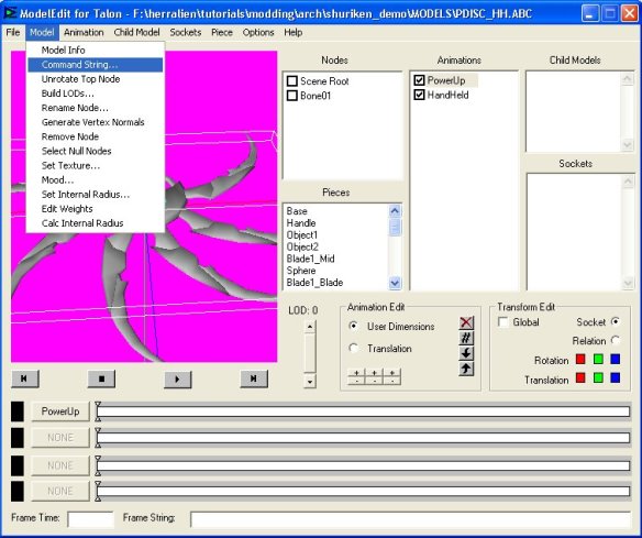
So far, the attached models can follow the sockets only if the amplitude of the movement is small. Even for small movements, the attachment still looks like it’s floating over the original model. To fix this behavior, you must set the FOV offset of the attached .abc model to 0, 0. To do this, you must set the final command string of the model to FOVXOffset 0; FOVYOffset 0; So, open the .abc model of the attachment, and select Model->Command String:

medit_fov1

Put the value of 0 in both FOV Offset fields (for both X and Y):

medit_fov2

Save the model and you’re done …

The archive

The archive contains a small .rez file and the document. The .rez has a small custom map, for testing. It can be accessed from the custom level menu, after placing the .rez in the command line. Enjoy.

Evac Lights

Need a SP/MP map to turn scarier? Well, besides turning all the lights off, you should really consider placing some evac lights. You know, those runaway lights that show you the closest evacuation point; you’ve seen them in Alien: Resurrection, when Call ‘asks’ the aliens to go for that corp dude.

Anyway, this prefab will give you just that: an evac lights system that stretches for 2560 units. 10 light elements (actually scale sprites) that turn on and off in a manner that will give the impression of runaway lights:

evac_lights0

So what we’ll do is turn on sprite group 0, keep it on for 0.1 seconds, that turn it off; at the same time turn on the group 1. After 0.1 seconds, turn it off and move on to group 2, then group 3 and so on until we reach group 9. Then back to group 0 and keep the loop running.

Each of those 10 elements is spaced 256 units from the next one. The placement will give you the illusion of runaway lights.

To make things a little bit more dramatic, I’ve added a SoundFX that gets triggered each 4 seconds. The alarm sound itself is 3 seconds long, so you’ll get 1 second of silence.

Anyway, back to those lights. Each element has the following objects:

evac_lights1

  • a group object; it sends the message it receives to all 4 sprites
  • the ‘On’ trigger. This one sends it’s messages delayed according to it’s placement. The On0 will have a 0 sec. delay, On1 will have 0.1 sec. delay, On2 – 0.2 sec. and so on. It also triggers the ‘Off’ trigger
  • the ‘Off’ trigger will turn of the sprites 0.1 sec. after being triggered. Period.
  • the sprites

What we’ll do is send each second the trigger messages to ALL the On  triggers. Depending on their ‘SendDelay’, each trigger will then turn on their sprites. Sending the message each second will be the responsibility of a trigger loop, like the one used in the AI Escort prefab.

Regarding the On trigger, best thing to do is to show you the settings for the On3 trigger:

evac_lights3

The ‘Off’ trigger simply sends the OFF message to the group object exactly 0.1 seconds after it was triggered. It’s ‘SendDelay’ dictates how long the sprite stays on:

evac_lights4

The Group object simply repeats the message it receives to all the objects listed:

evac_lights5 evac_lights1

In our case, Group0 will control ScaleSprite0 to ScaleSprite3.

So, all we need now is a loop that triggers all On triggers each second. That’s exactly what the red underlined triggers do:

evac_lights2

There are two loops here: the blue one that controls the SoundFX object and the one in red, that maintains the sprites turned on and off.

However, because I needed to close the loop and the fact that the trigger object has only 10 targets, I had to add another trigger called next to handle the last two On triggers.

Without being underlined, the control triggers start/stop all loops by locking/unlocking and triggering one trigger from each loop. Settings and targets for each trigger as follows:

ELTrigger:

evac_lights6

The last target from ELTrigger’s list is the ‘Next’ trigger:

evac_lights7

As you can see, it has no delay; it’s merely an extension for ELTrigger.

This is the ‘CloseLoop’ trigger for the one second loop:

evac_lights8

Remember, the period is always the sum of the delays:

 0.5 sec (the ELTrigger) +
 0.5 sec (the CloseLoop)
 ------------------------
 1 second period

So, although the send delays for these two triggers were 0.5 seconds, because only the ELTrigger sends the trigger message to the On triggers, you’ll get the sequence wanted.

The 4 seconds alarm sound loop:

evac_lights9 evac_lights10

And the SoundFX itself:

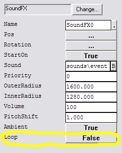
evac_lights11

Select the appropriate sound. I went for the ‘alarm.wav’ sound. It lasts 3 seconds. That and the 4 seconds loop will give you one second pause.

Now when you have more SoundFX objects and you want to make sure the FX gets heard give it higher priorities. They range from 0 to 2.

Now we don’t want this one to loop! We have our triggers handling this one, remember?

The ‘EvacLightsStart’ and ‘EvacLightsStop’ triggers? Well, I’ve said earlier what they do, but I’ll throw in another couple of pictures:

EvacLightsStart:

evac_lights12

EvacLightsStop:

evac_lights13

To make things sweeter, I’ll throw in a .zip file. This one is 100% copy-paste compliant, so you can use several of this babies in the same map.

Numeric code lock

You have seen them in Doom3 for example; basically a keypad in which you had to type in a code to perform specific actions: gain access to health and ammo, enter specific rooms etc.

The impact of these locks on gameplay was very powerfull. In my case, for example, it had me searching for PDA’s like crazy. I also ended up giving more atention to the background story. Now although the interface used in Doom3 cannot be used in AvP2, locks which operate with codes might have the same impact: the player paying more and more atention to the story, reading PDA’s and notes in hope of finding a code, a code which will give him the health and armor he desperately needs.

  • 29 triggers, 16 TranslucentWorldModel and 10 switches. This is what it took (in my case) to have something very similar in AvP2. The features gained are as follow:
  • the lock will be opened if you punch in a series of 3 digits
  • by default, the lock cannot be used again: once it unlocked the resources it was guarding, it will remain unlocked.
  • the lock doesn’t care about the succesion of the digits.

Although this last mention might look like a serious bug, please take this into account: chances of guessing the digits of the code (no matter the order in which they are placed) is almost 1 in 1000. Now, punching in a combination takes at best 2 seconds. Nobody will try for 2000 seconds (33 minutes) to crack a lock: you will need the code.

Due to the complexity of the prefab, I will first explain how to integrate it into a map, how to set a password and what to change after a COPY-ALT-PASTE operation. For reasons that elude me at this point, triggers are copy-paste friendly. Switches and pretty much anything else are not. This does affect our lock. After a copy-paste operation, you will first have to edit the switches of the lock:

lock0

To be more accurate, you will have to change the LockedCommand string to point to the right trigger:

lock1

lock2

And you will have to do this for all 9 switches, so that SkX_Ln will point to the show_kX_Ln: kX will tell you which key you are editing, while Ln will tell you to which lock this key belongs. Now, after a copy-paste operation, regarding the switches, the only thing that needs to be edited is the index of the lock (Ln), as shown in the above pictures. The indexes of the keys are safe. After editing the switches, it’s time to set up a password. The focus changes from the switches, to the triggers targeted by the switches:

lock3

For example, if we want to include the digit 0 in the code for lock 1, we will have to edit the trigger targeted by Sk0_L1, and that one (again as shown in the pictures above) is called Show_k0_L1. You will be able to find it in the node view in the path Triggers/ButtonAnim/k0_.

The next thing is to have this trigger unlock one of the 3 control triggers of lock 1: FirstKeyOK_L1, SecondKeyOK_L1 or ThirdKeyOK_L1.

lock4

In our case, FirstKeyOK_L1:

lock5

Linking in this way show_k4_L1 to SecondKeyOK_L1 and show_k7_L1 to ThirdKeyOK_L1, you have the following codes allowed: 074, 047, 407, 470, 704 and 740.

The last thing needed is to have the lock actually doing something. For this, we will edit the UserOpen_L1 trigger. As the name says, this is the trigger that should be used to have the lock 1 linked to an action:

lock6

In our sample, we will turn on the lights in our map.

I’ve prepared two goodies: the regular archive (containing the .ed file, the textures needed and this very page) and a small-one-room map. Enjoy.

AvP2’s Zombies

Inspiration strikes

Currently I’m playing S.T.A.L.K.E.R. and I have to admit, I am impressed. Although zombies are being (over)used quite a lot, they still remain scary. I mean they are not alive, but also not quite dead. There is a difference in between ‘breeds’ of zombies encountered in games and movies: most of them move slow, talking nonsense or just moaning. The zombies from Doom 3 and Return to Castle Wolfenstein however, had another feature that scared the pants off me: they resurrected.

Yep. You saw some bodies lying on the floor, looking “all nice and dead”, and as soon as you pass them by they get up and start hurting. You. They start hurting you. This is what I had in mind with this prefab: you walk across a hallway, and all of a sudden you spot your enemies. Obviously, you start rotating the barrels of the minigun and lay waste on them. You move forward, and just when you’re about to pass them you see something that sends chills down your spine: your ‘victims’ are slowly standing, and, after a minor inspection of themselves, they move to attack.

One possible sollution

The structure I settled for has the following elements:

zombie0

Zombie0 is the actual AI unit. All other elements (PlayDead0, Resurrect0, StartFeeling0, StopFeeling0) are triggers. The functionallity of the prefab can be described in the following steps:

  • each time the AI unit takes damage, it triggers PlayDead0
  • after a number of messages received, PlayDead0 finally triggers
  • PlayDead0 makes the zombie play a death animation. At the same time, the StopFeeling0 and Resurrect0 triggers get triggered.
  • StopFeeling0 simply locks PlayDead0. This way, further damage cannot trigger another death animation
  • Resurrect0 sends it’s message 10 – 20 seconds after being triggered. This delay corresponds to the durration of the zombie “playing ‘possum”. The messages send by this trigger will cause the zombie to play the “get up” animation. A second message will trigger StartFeeling0.
  • StartFeeling0 simply unlocks (with a delay of 10 seconds, the time needed by the zombie to get up) the PlayDead0 trigger.

The triggers

Actually, we need to start with the AI unit itself:

zombie1
As you perhaps already guessed, the AI has NEVERDESTROY set to true. However, it will process damage (CanDamage=TRUE). The message set each time the unit is damaged will trigger PlayDead0. Speaking of the devil, the settings for PlayDead0:

zombie2

And here are some features, making the behaviour of our zombie quite interesting:

  • first of all, the trigger will ignore the message that comes within 1 second from the previous.
  • neither the player nor the AI are allowed to trigger it
  • it will wait for 5 messages before triggering

These settings will allow you to “kill” the zombie in about 5 seconds of gunfire; there is no distinction between a shotgun (which packs more punch per round) and the Pulse Rifle. These settings will make the zombie tougher or softer.

As I mentioned earlier, PlayDead0 also sends some messages:

zombie3

The most important is, without a doubt, the message sent to the AI unit:

killscripts; scr (igd; pa Death_H; pla Collapse2)

First, terminate all running scripts. Then make the AI ignore damage (igd) and then ask him to play the fall animation (pa Death_H). Finally, keep the AI facing the ground with the last command (pla Collapse2). While lying down, the AI is still executing the script: no “end;” statement at the end of the script.

I already mentioned Resurrect0. Here are it’s basic settings:

zombie4

SendDelay of 10 is the ammount of time the zombie is lying face down.

The messages sent by this one are as follow:

zombie5

The first message is more interesting; it is sent to the AI unit:

scr+ (pa Collapse2_Getup; end)

Basically, it uses the script started by PlayDead0 and it asks the AI unit to get up.

The StopFeeling0 trigger is set up like this:

zombie6

It simply locks the PlayDead0 trigger (see above).

The StartFeeling0 trigger unlocks the PlayDead0 trigger and resets all the senses of the AI unit. Reseting the senses is not mandatory, but I decided to add it:

zombie7

The 10 seconds delay generated by SendDelay are needed to allow the AI unit to finish it’s animation; basically PlayDead0 shouldn’t take into account damage taken by the zombie while it’s defensless. Plus, it’s scarrier >:) .

The prefab is not fully copy-paste compliant; if you plan to add more zombies, make sure that the damage field from the AI unit points to the appropriate PlayDead trigger: Zombie1 should send it’s damage messages to PlayDead1, Zombie2 should send it’s damage messages to PlayDead2 and so on.

As usual, the archive contains both the .ed file and this very web page.

Of course, custom characters and AIButes can (and should) be added in the Attributes files, so that the zombies will moan and move slower and so on. I thought also of making a small map, using Michale Jackson’s “Thriller” as soundtrack, but I’ll leave that up to you.

Directional Triggers

First thing: a directional trigger is a prefab that sends one message while the player goes thorough it in one way and another message if the player passes through it in the opposite direction.

Ok, now what uses can the average Avp2 mapper find for this contraption?

Well, for start, one of this babies can change the music played in a SP mission. Place it at the entrance to one section and make it send messages like ‘msg player (music DefaultMood Ambient AmbientX)’ when the player goes in one way and messages like ‘msg player (music DefaultMood Ambient AmbientY)’ when he goes back.

Another thing this baby can handle is sending visibility messages like ‘msg NiceTerrain0 (visible 1)’ or ‘msg NiceTerrain0 (visible 0)’ to make a SP level run at (very) high frame rates, despite the high poly count for the terrain mentioned.

What I came up with is a set of 6 triggers:

dir_trigger2dir_trigger1

The core holds the triggers the player actually touches (called ‘Sensors’) and two additional triggers, that lock and unlock the sensors. The other two triggers are the triggers that should be used by the mapper. Simply place all your messages there. Set up delays etc., I don’t care; you can make all the alterations you want, these are the triggers that will receive trigger messages from the core. So if something goes wrong, you’re the only person to blame 🙂

As you’ll see from the scripts below, the working of this DirTrigger is pretty simple:

  • as the player moves one way, it touches one sensor and then the other.
  • The sensor touched first will trigger the FBLockAll0 trigger and thus
    lock itself and the second sensor. It also triggers the timed trigger
    FBUnlock0, to unlock both sensors after the player has moved away
    from it (2 seconds). The last target the sensor has it’s his own
    trigger, in our case say Trigger_goingForward0.
  • when the player reaches the second sensor, he/she ‘ll find it locked
    (remember? the first sensor touched locked it!). Thus, his own messages
    will not be send.
  • going the other way, the player will touch the second sensor first and reach the first one while locked and so on.

The scripts are pretty simple. These are the settings for one of the two
sensors:

dir_trigger3dir_trigger4
The other sensor is almost identical, except the last target, which will be
Trigger_goingForward0.

Settings and targets for the FBLockAll0 trigger:

dir_trigger5dir_trigger6

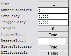
The reason why I set the PlayerTriggerable to FALSE is simple: the trigger lies in the middle of the contraption so it might get touched by the player; but I don’t want the player to trigger it, I want the sensors to do it.

Settings and targets for the FBUnlockAll0 trigger:

dir_trigger7dir_trigger8

Remember? The Unlock trigger must be timed!

What can I say in the end: the .zip file has three such triggers, for each 3 possible directions:

  • front <-> back
  • left <-> right
  • up <-> down

The way they were build allows you to copy-paste them repeatedly, without worrying about the scripts and the fact that all the CORE sections will trigger the same triggers; they are completely isolated and ‘copy-paste’-safe.

Portable sentry guns

Let’s make one thing clear. ALL pickups in DEdit that can be placed down WILL ALWAYS BE PLACED DOWN IN THE SAME LOCATION THEY WERE PICKED UP. Period.

What will a regular gamer expect from a portable turret?

  • he will expect that by hitting his use key, the turet to be picked up (disappear from his view).
  • when arriving to an appropriate point, he’ll expect that by hitting his use key again, the turret will appear and become active.

That’s exactly what you have to achieve. Sure, some limitations may appear, but as long as the main thing is accomplished, it’s unlikely someone will complain. So, in ‘Take 1’ I’ll just explain how the gamer can be tricked into believing he actually carried a turret (or two in our case) from point A to point B.

The harsh reality of ‘Take 1’

turrets1

Yes! Yes! There are actually 8 turrets there! The mere fact that you can see only two helped me to create the illusion that you can carry two turrets. So, the first prefab gives you 8 possible places where you can place one of the two visible turrets.

Describing the problem

How can one modder make sure that from N possible active items [turrets] only maximum two are active at any given moment?

‘Take 1’ solution

The structure I settled for a portable turret had three elements:

turrets2

  • the turret itself
  • two switches:
  • one that made the turret visible and active; placed on the floor. Becomes invisible after it has been activated.
  • another one that made the turret inactive and invisible; placed somewhere in the air. Becomes invisible at the same time like the turret.

Initially , you only have two turrets and their THide switches visible.

So what I did was to make a turret invisible and inactive in point A (say activated THide0), and then make another turret visible and acive in point B, by activating say TShow3. The gamer would belive that he actually carried the turret from point A to point B!

However, if you also activate TShow4 (say in point C) and TShow7 (in point E) you’ll have 3 visible turrets. But you only had two turrets! A counter is needed.
The final structure had 8 turrets each with their two switches, an event counter and two triggers (one hiding all TShow switches and another one showing them).
You should scatter the 8 turrets across the map.

The scripts

The switches have to send only one message, either they are triggered open or close. So, I locked all the switches and used the ‘Locked command’. Here are the strings for a THide switch:

turrets3

  • we decrement the counter that counts how many turrets are available
  • we inactivate the turret and hide both the turret and the switch.
  • make visible the corresponding TShow switch (the location is now available to ‘place’ the turret you’re ‘carrying’)

and a TShow switch:

turrets4

  • we say that we placed another turret ->increment the counter that counts how many turrets are available
  • we unhide both the turret and the switch. Turn on the turret – make invisible the corresponding THide switch (you already picked up the turret, you can’t pick it up again!)

The script for the EventCounter (named here TurretCount0) is the following:

turrets5

Sure, the starting value is not a script component. However, if you bare in mind that you need only a given number of turrets visible, setting this at 2 will tell us that when we reach 2, there shouldn’t be any TShow switches visible (all the turrets are placed). As soon as we drop below 2 (meaningvthat we’ve picked up a turret), we should show all the TShow switches.

If you don’e belive me, take a look at the script for the switches again: THide (pick-up) decrements the counter and TShow (put down) increments it. So, when we reach 2 through incremental ascension, we’ll hide all the TShow switches:

turrets6

However, as soon as we drop below 2 (at least one turret picked up) we should unhide all the TShow switches:

turrets7

HideAll0 is a trigger that sends the message (hidden 1) to all the TShow switches (TShow0, TShow1 etc.) so that after you’ve placed all your turrets you won’t be allowed to even try to place more turrets than initially visible.

ShowAll0 does exactly the opposite. Right after you pick up one turret, this trigger will send the message (hidden 0) to all the TShow switches; this way you’ll be alowed to place it down.

That’s about it. Feel free to use the prefab. The .zip file is here. (” … I push my fingers into my eyes … “) Best of luck, and I HOPE YOU’LL MAKE IT 🙂

09th of September 2006: Sentry gun prefab update [March 2005]

The update regarding ‘NEVERDESTROY’:
It seems that although the sentries are set to neverdestroy, at least in MP
they can be destroyed [it seems that also taking the map with them 😦 ].

Actually, the problem resides in the AIButes.txt file.
You should increase the hitpoints for the base turret:

..............
 [BasicTurret]
 HitPoints = 1000000.0

BurstSpeed = 10

AwakeSound = "Sounds\Events\Ed_SentryTurn01.wav"
 DetectSound =
 "Sounds\Weapons\Marine\SADAR\sadarlock.wav"
 MoveSound = "Sounds\Events\Ed_SentryTurn01.wav"
 ..............

This should keep them from beeing destroyed.

Simple AI Escort for AvP2

The following prefab is a simplification to the original AI Escort prefab; it has less triggers, without affecting too much it’s performance. I don’t know whether I’ve stated this before or not, but this page CANNOT REPLACE modmaker’s tutorial and the docs that came with the tools (I’m talking about the avp2_AI_notes.doc file). Read them if you plan on expanding this prefab; you’ll need some info about AI Volumes and AI commands that can be found in those docs. If you’re only after a copy-paste prefab, or you’re experienced enough with AvP2’s AI, you can skip them.

Describing the problem

The problem itself is the same: what does an escort actually do? It follows the player anywhere he/she goes and, when spotting an enemy, opens fire. The AI that escorts the player must be able to receive orders like ‘Follow me’ and ‘Hold ground’. Either way, the AI must attack any enemy within his range. So all we have to do is to give our AI an iddlescript and tell him to run towards the player by sending it the message:

killscripts; iscr(run; mt player; end;)

We can continuously send this command using some sort of loop. The fact that it’s an iddlescript will allow the AI to break the script to engage enemies. Although it’s something that we want, it does have one bad effect: the AI, having the script terminated by engaging the enemy. However, the next message will tell it to move on. How do we ‘persuade’ this pesky marine to stop following us? Well, that’s easy: kill its scripts (the ‘killscripts’ command) and terminate the loop. To make it follow the player again, give it a script and restart the loop

Looped triggers

Place two triggers, both of them with a ‘SendDelay’ of one second and make
them trigger each other: triggerA should have as target triggerB and
vice versa. Trigger any of them and you’ll get a 2 seconds period loop. Each
two seconds triggerA gets triggered. To break the loop, send the ‘lock’
message to one of the triggers. To restart the loop, send the ‘unlock’ message
to the locked trigger and then trigger any of them. That easy.

In our case, we’ll need just one loop.

The scripts

The following images contain explicit scenes and should not be viewed by any audience. This images are for mappers’ eyes only 🙂 First, the structure of one AI escort unit:

simple_escort1The EAIMarine0 is the A.I. unit that gets to follow your ass. loopA0 and loopB0 make up the ‘short-fused’ loop.
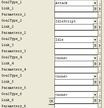
FollowMe0 unlocks the loop and restarts them after starting a new script. HoldGround0 does the opposite: kills all scripts and locks the loop. Here are the settings and commands for the AI unit:

escort2
I know this is a little bit unusual, but I’ve set the AI unit to be indestructible. That was  achieved by setting the ‘NeverDestroy’ flag to TRUE (see ‘DamageProperties’ for the AI unit).
However, the interesting part takes place in the ‘Commands’ section and the goals selected in ‘Goals’. As you can see, I choose only the ‘Attack’ and ‘Iddlescript’ goals:escort3

The third goal makes the AI look more natural while standing still. The other stuff I was talking about is the ‘Commands’ section. Placing messages in here will allow you to use the AI unit much like a switch:

escort4

So, if we press ‘USE’ while facing EAIMarine0, we’ll trigger either FollowMe0 or HoldGround0.

As stated earlier, these two triggers unlock and start the loop or do the opposite. The settings and targets for the FollowMe0 trigger:

simple_escort5

What does it do? Unlocks and starts the ‘short-fused’ loop that sends the iscr messages. It also starts the iddlescript for the AI unit, makes it say something and allows it to move anywhere (leash length is set to 0).

The loop has the loopA0 trigger and loopB0 trigger. Those two are almost identical, except the last target. The settings and targets for the loopA0 trigger:

simple_escort7

The loopB0 trigger has it’s second target set to loopA0. Except that, they’re twins.

From ‘HoldGround0’ we’ll expect to kill all scripts and lock one trigger in our loop:

simple_escort6

And you were right; it also makes the AI say one phrase and gives him a 384 units leash around the point it was ordered to guard. If you plan to add more units like these, the only thing you should be aware of is to change the ‘Commands’ section so that EAIMarineXX sends his messages to FollowMeXX and HoldGroundXX. The triggers themselves are excellent connected, so you won’t need to change anything there when copy-pasting folders containing units like these; your only concern will be the ‘Commands’ section. So, copy-paste whole folders and change the ‘Commands’ section for each AI unit.
It may rarely happen that even after you’ve told the marine to hold ground, it may still follow you; that’s because the other trigger already got … triggered and it was only a matter of time (those 3 seconds) until it managed to send it’s messages. You can shorten this amount of time; however, you’ll be starting and ending too many scripts per second, so it may cost you extra CPU. It’s a nasty choice: better AI performance vs. better overall map behavior. Three seconds were a good compromise. However, feel free to toy with this; remember, the power of the computers grows every year.

The .zip file hosted on GoogleDrive will have both the .ed and this .html page. The .ed file is a small map, that has one EscortUnit and a multispawner, triggered by 4 wall
switches. Toy with your escort, make him guard you or their last position with or without enemies. See how they behave. Expand it by means of Copy-Alt_Paste and editing the ActivateOn and ActivateOff fields in the Commands section.

Hopefully, this will spell the end for those SP missions that left you alone to deal with your enemies.

Changing the character model hitbox for AvP2

The purpose of this tutorial is to illustrate how to change the hitbox for a character model in AVP2. This is a must do, especially since some of the animations of the model will take certain parts (like the head, and sometimes half the torso as well) outside of the hitbox, making multiplayer a sometimes frustrating experience.

The following applies the same for all character models: predators, drones, runners, humans and so on.

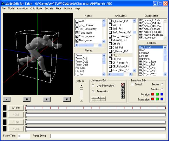
Open up ModelEdit. Load an existing model (multi player character models are located in <game_folder>\AvP2\Models\Characters\MP), and select (in the options menu) to make visible the user dimensions:

User Dimensions - another name for hitbox

Now, select an animation, and start working. In our example, we chose to alter the “Crouch – move forward – with a pistol” animation (CF_Ps1):

In the “Animation Edit” box, make sure that the active radio button is ‘User Dimensions’. This will allow us to change the size of the hitbox by pressing the six “+” and “-” buttons located just below the radio button. In our case, we’ll increase the size on the Z (forward-backward) and Y (vertical) axes. So, press the second “+” button (for Y) and the third “+” button (for Z) until reaching an acceptable size:

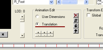
At this point the hitbox looks OK in terms of size. However, the head is still outside it, and so are the character’s arms. We need to translate the animation so that it fits nice in the hitbox. To do that, change the radio button in the “Animation Edit” box from “User Dimensions” to “Translation”:

Now the six “+” and “-” buttons will work differently: they will shift the animation. In our case we need to move it back on the Z axis (press the third “-” button) and lower it down a bit (negative Y, meaning press the second “-” button), until you get something like:

Now, move the animation slider, or press the play button and watch how the animation and hitbox work together. Make some adjustments if needed, but in most cases even the changes made above will be a good enough step forward.

One thing to be remembered about character hitboxes: they are a trade-off. You will not be able to make it small and have all body parts inside it. But if you have the head, torso and at least half the arms and legs then the hitbox will do just fine.